

1. What Does a Data Center Look Like?
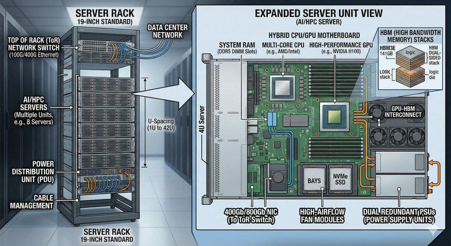
To train AI, thousands to tens of thousands of GPU chips must run simultaneously. These GPUs don’t work alone — they constantly exchange data with each other in a collaborative process. A data center is simply where all these GPUs live together.
It’s easy to picture a data center as one giant computer, but in reality it’s built by stacking small, repeating units. That basic unit is called a rack.
A rack is a metal cabinet-style frame, roughly two meters tall, with multiple servers slotted vertically inside. Think of a server as a computer housing several GPU cards — typically four, eight, or sometimes dozens per server, alongside CPUs, memory, and storage.
Racks don’t just hold servers, though. Network switches live in there too. A switch is essentially a traffic controller: it collects data from the servers in the rack, organizes it, and sends it outward. Because switches usually sit at the top of the rack, they’re called ToR (Top of Rack) switches.
Multiple racks line up in a row, and multiple rows come together to form a section of the data center. The reason for this structure is straightforward — power distribution, cooling, cable management, and maintenance are all standardized at the rack level. Even the most powerful AI systems ultimately sit on top of this same rack-based foundation.
2. How Does Data Move? Inside the Rack and Beyond
Having tens of thousands of GPUs means nothing if they can’t talk to each other. GPU communication generally breaks down into two segments, and because the distances differ, so do the methods.
Short distances (Scale-up Network): Where copper has the advantage
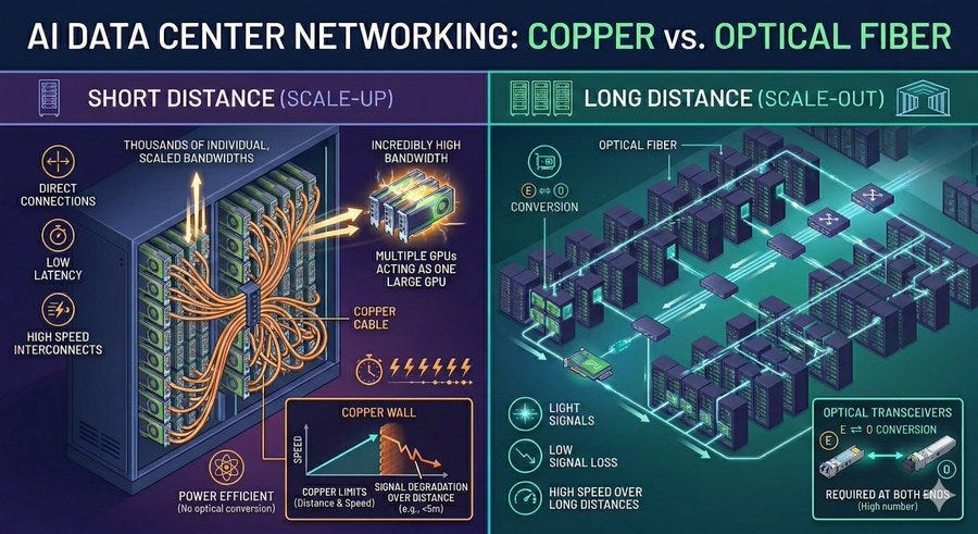
For short runs — within a single rack or between adjacent racks — sending electrical signals over copper cable is the practical choice.
When GPUs within the same rack communicate, they use dedicated high-bandwidth interconnect technology that links dozens of GPUs directly to one another. The speeds involved are in the hundreds of GB/s to TB/s range per GPU, effectively turning a cluster of GPUs into one massive processor. This is called the scale-up network.
The same logic applies to GPU-to-switch connections inside the rack. Cables here typically run two to three meters, and copper handles that just fine. At today’s 800G speeds, passive copper cables (DAC) can reach around three meters, while active copper cables (AEC) stretch to about five.
Copper’s advantages are clear: simpler components, no expensive optical conversion hardware, easier maintenance, and better power efficiency at short distances.
That said, copper feels the strain as speeds climb. High-speed electrical signals degrade and distort as they travel through cables, connectors, and circuit board traces. The faster the signal, the worse the degradation, and the more complex the correction circuitry needed to compensate — which means more power and more heat. What once worked with any copper cable now demands tight tolerances on cable quality, connector precision, and compensation circuits. The usable distance for copper keeps shrinking as speeds rise. This is what the industry calls the “Copper Wall.”
Long distances (Scale-out Network): Where fiber becomes essential
Longer runs change everything. Once you’re spanning more than a few meters — crossing between racks in the same row, connecting racks across the hall, or stretching hundreds of meters across a data center floor — copper simply can’t do it. Optical fiber is the standard.
Training large AI models requires thousands to tens of thousands of GPUs, which means dozens to hundreds of racks need to be interconnected. This is the scale-out network, also called the backend network. Each GPU has a network interface card (NIC) that connects to a switch, and those switches connect upward to higher-level switches, eventually forming a fabric where any GPU can reach any other GPU. A large portion of these scale-out connections run over optical fiber.
Fiber’s strength is distance. Light travels long runs with almost no signal loss, and higher speeds don’t shrink the reach the way they do with copper. The cables themselves are also thin and lightweight, which makes routing and cable management much more manageable.
There’s one added step with fiber, though. Since GPUs and switches operate on electrical signals, the signal has to be converted to light before transmission and converted back to electricity upon arrival. The device that handles this conversion is an optical transceiver, commonly called an optical module. One sits at each end of every connection. In a data center with hundreds of thousands of GPUs, that adds up to millions of optical modules.
The bottom line: short distances (within a few meters) use copper, long distances (tens of meters and beyond) use light. In between, either can work depending on speed and conditions, but the range where copper holds up keeps narrowing as speeds increase. That’s the operating principle behind today’s data centers.
3. The Actual Path Data Takes
Section 2 laid out the big picture: copper for short runs, light for long ones. Now let’s trace the actual path data follows step by step, because understanding this path is what makes the bottlenecks visible — and explains why CPO matters.
Scale-up: GPU-to-GPU communication within the same rack
The path for two GPUs in the same rack talking to each other is relatively simple:
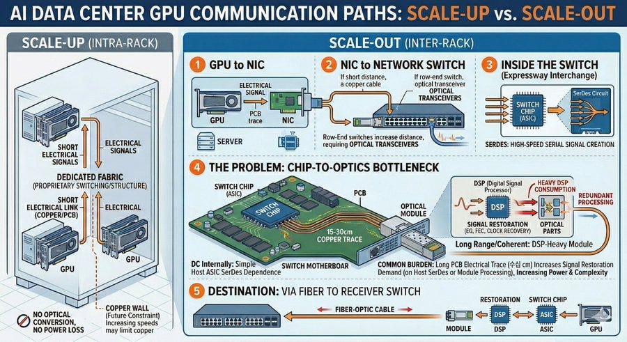
GPU → copper cable → switch chip → copper cable → GPU
Distances are short, so the whole thing runs on electrical signals, handled by copper cables or board traces. There’s no need to convert anything to light, so no optical modules, and none of the power losses that come with electrical-to-optical conversion.
That said, this segment won’t stay copper-only forever. As bandwidth keeps growing, the distance electrical links can reliably cover keeps shrinking, putting more pressure on cables, connectors, and compensation circuits. Eventually this segment will hit copper’s limits too — more on that later.
Scale-out: Communicating with a GPU in a different rack
When a GPU needs to send data to one in another rack, the path becomes considerably more involved.
Step 1: GPU to NIC
Data generated by the GPU first goes to the network interface card (NIC) in the same server. This is a short internal path handled entirely by board traces, so electrical signals are fine.
Step 2: NIC to network switch
The electrical signal leaves the NIC and travels via cable to the network switch. Whether this uses copper or fiber depends on distance and physical layout. If the switch sits at the top of the same rack, copper usually works. But if the switch is located elsewhere — which is increasingly the case in newer data center designs — this segment may already require optical connections.
Step 3: Inside the switch
At the heart of the switch is a specialized chip called a switch ASIC. Think of it as the interchange on a highway — it takes incoming data and routes it toward the right destination.
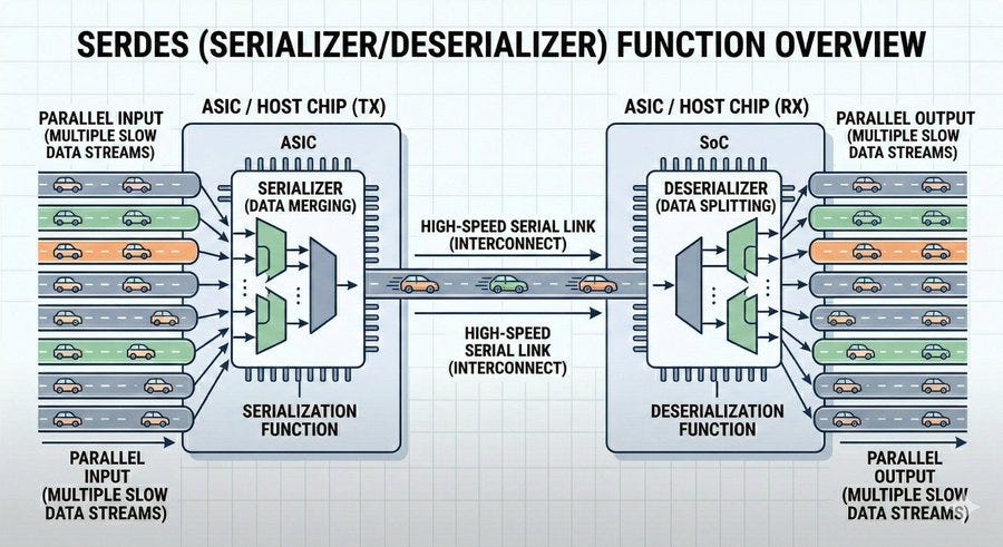
Inside the switch ASIC is a circuit called SerDes. SerDes takes the chip’s internal data and converts it into a high-speed serial signal to send outward — similar to merging multiple lanes of traffic into a single fast highway lane.
Step 4 (Problematic one): Switch ASIC to front-panel optical module
The high-speed electrical signal coming out of the switch ASIC doesn’t get converted to light immediately. Instead, it travels across the switch’s circuit board — roughly 15 to 30 centimeters — before reaching the optical module plugged into the front panel.
That “15 to 30 centimeter electrical stretch” is where problems pile up. High-speed signals degrade and distort even across short distances, so before or inside the optical module, the signal has to be cleaned up.
For those less familiar with the technical details, here’s a simplified way to think about it as one bundled process:
Signal conditioning (DSP): Restores distorted waveforms to a readable state.
Clock recovery: Re-establishes the timing reference for when to sample the signal.
Retiming: If needed, regenerates the signal from scratch.
Forward Error Correction (FEC): Catches and fixes bit errors on the receiving end.
As distances grow and speeds increase, this “signal rescue” operation has to work harder and grow more complex. The conclusion is straightforward: the farther the signal has to travel electrically before becoming light, the more processing and correction it requires, and the more power and design complexity that demands.
Step 5: Fiber to the destinationLight travels through fiber to the switch on the other end. There, an optical module converts it back to an electrical signal, the switch routes it to the right destination, a cable carries it to the target server’s NIC, and finally the data arrives at the GPU.
The segment worth keeping in mind from all of this is Step 4 — the stretch of electrical signal traveling from the switch ASIC to the front-panel optical module across the circuit board. The longer that stretch, the heavier the correction burden and the higher the power consumption. Hold onto that picture, because the next section explains why that segment is such a serious problem — and how CPO changes it.
4. Why CPO Is Needed, and What It Changes
The core problem: The conversion point is too far away
Recall Step 4 from above. In the scale-out path, the electrical signal from the switch ASIC’s SerDes travels 15 to 30 centimeters across the circuit board before reaching the front-panel optical module. That 15 to 30 centimeters produces three specific consequences.
Power is wasted on a significant scale: the DSP inside a single optical module consumes roughly half the module’s total power, and across a large data center, optical modules collectively draw several megawatts. The front panel runs out of physical space: starting with the 102.4 Tbps generation, there simply isn’t enough room for all the ports. And millions of individual components each generate heat and each represent a potential failure point.
The scale-up side isn’t safe either. Copper works fine today, but double or quadruple the speeds and the Copper Wall becomes unavoidable. Extending GPU-to-GPU high-speed direct connections beyond a single rack already makes copper impossible — light becomes the only option.
Scale-out or scale-up, both paths point to the same underlying problem:
The electrical signal is traveling too far.
CPO: Co-Packaged Optics
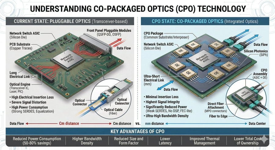
CPO (Co-Packaged Optics) attacks that distance directly. Rather than plugging optical modules into the front panel, it integrates the optical engine — the component responsible for converting electricity to light — into the same package as the switch chip.
The path comparison makes the difference obvious:
Before CPO: chip → (15–30 cm of board traces) → front-panel optical module → fiber
With CPO: chip → (a few millimeters) → in-package optical engine → fiber
The electrical distance drops from 15 to 30 centimeters to just a few millimeters. That single change sets off a chain reaction that reshapes everything else.
The SerDes changes. Previously, sending signals across 15 to 30 cm required powerful long-reach (LR) SerDes with complex equalization circuits and high power draw. With CPO, signals only travel a few millimeters, so low-power extremely short reach (XSR) SerDes is sufficient. Simple correction circuits are enough to maintain signal quality, and this alone cuts power meaningfully.
The DSP shrinks or disappears entirely. In conventional optical modules, the DSP consumed roughly half the module’s power because signals arriving after a 15 to 30 cm journey were heavily degraded. After just a few millimeters in a CPO setup, the signal arrives nearly intact. The DSP can be eliminated completely (DSP-free) or stripped down to just forward error correction (FEC-only, or DSP-lite). This is the single largest source of power savings in CPO.
The front-panel constraint disappears. With optical modules no longer occupying front-panel slots, port count is no longer limited by panel surface area. The same switch can expose significantly more ports.
Component count drops. Instead of dozens of independent optical modules, a few integrated optical engines handle everything in the switch package. Fewer failure points, higher system reliability.
The net result is 50 to 80 percent lower power consumption, with higher bandwidth and more ports from the same switch.
Where things go from here
CPO is being deployed first in scale-out network switches, because that’s where the bottleneck is most acute right now.
The next step is CPO at the NIC level. As noted earlier, newer AI data center architectures are moving switches out of individual racks, which means the NIC-to-switch connection increasingly requires optical modules too. Integrating optical engines into NICs would reduce power consumption and component count in this segment as well.